Heavy Duty Female Rod Ends from Wixroyd
What is...
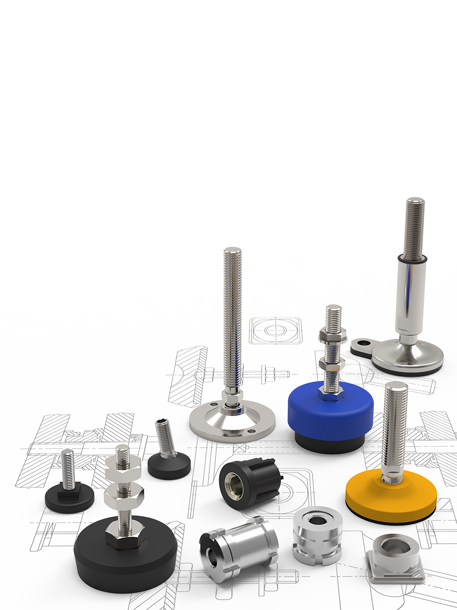
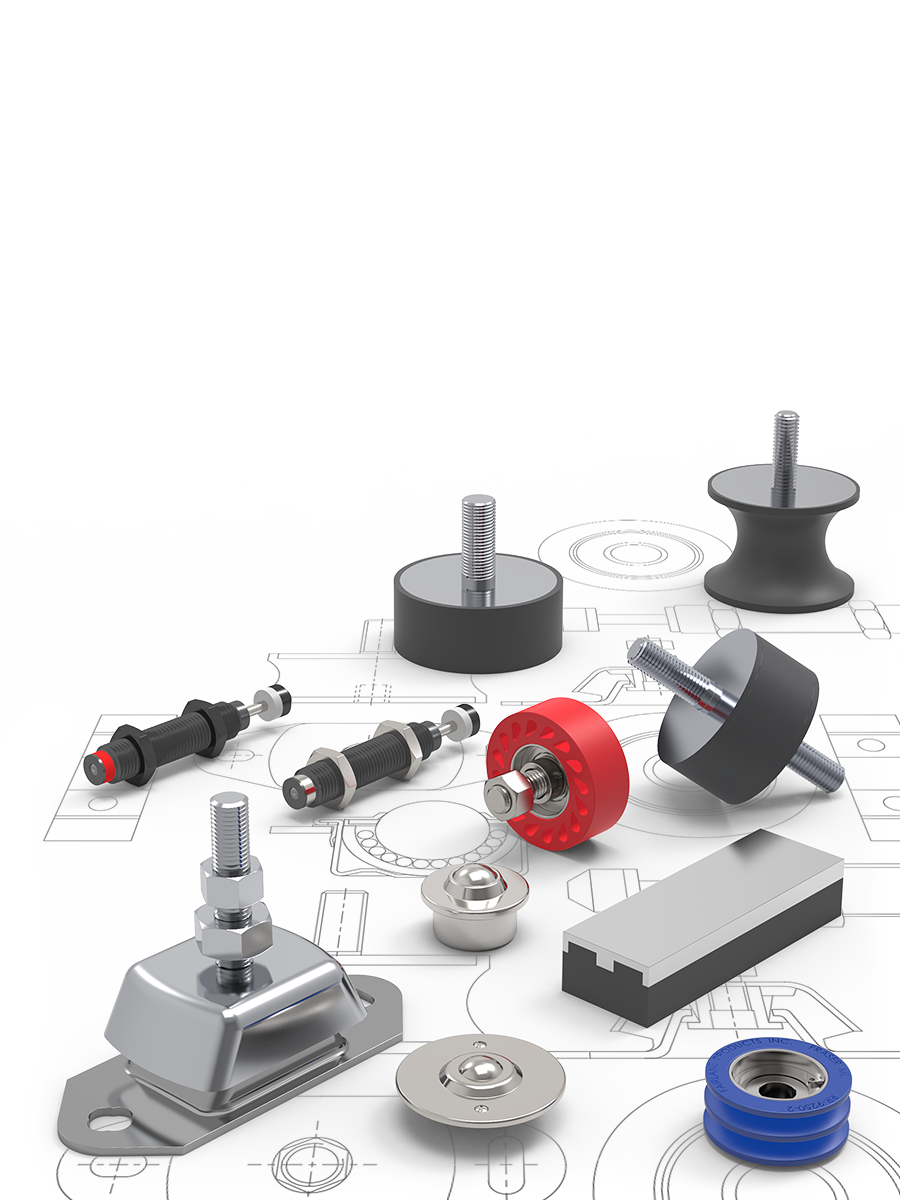
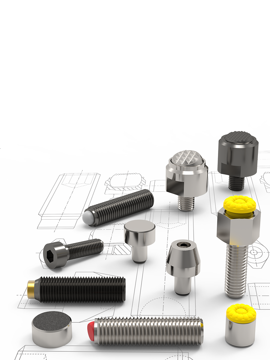
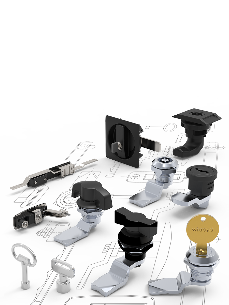
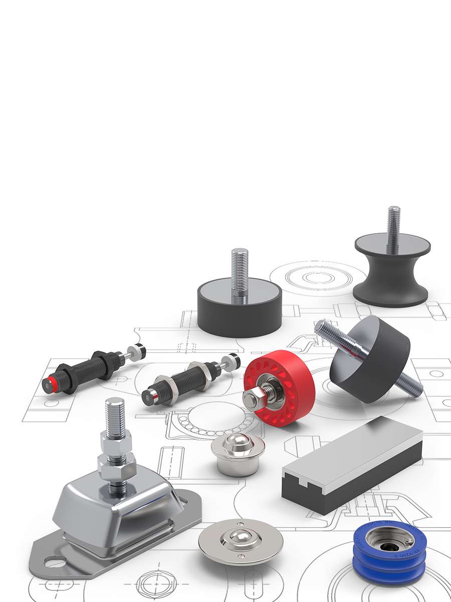
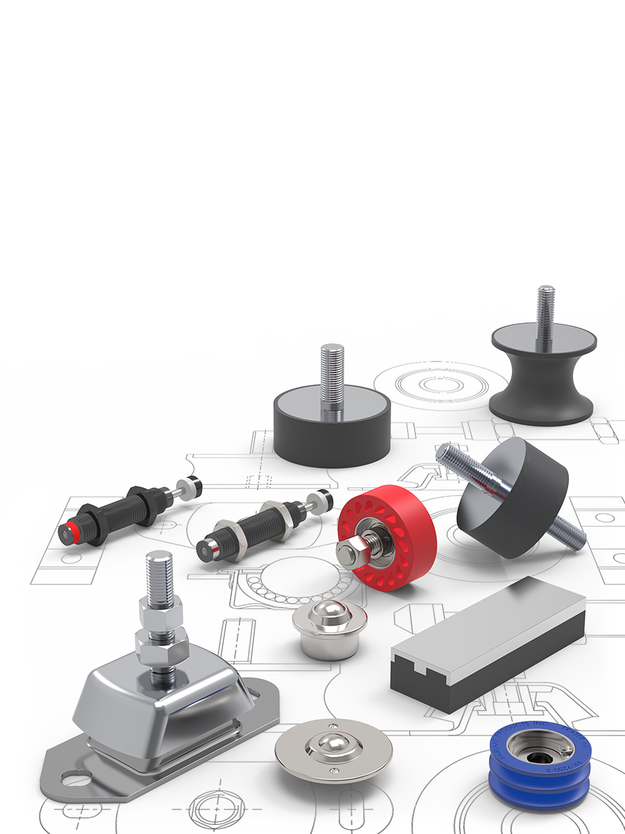
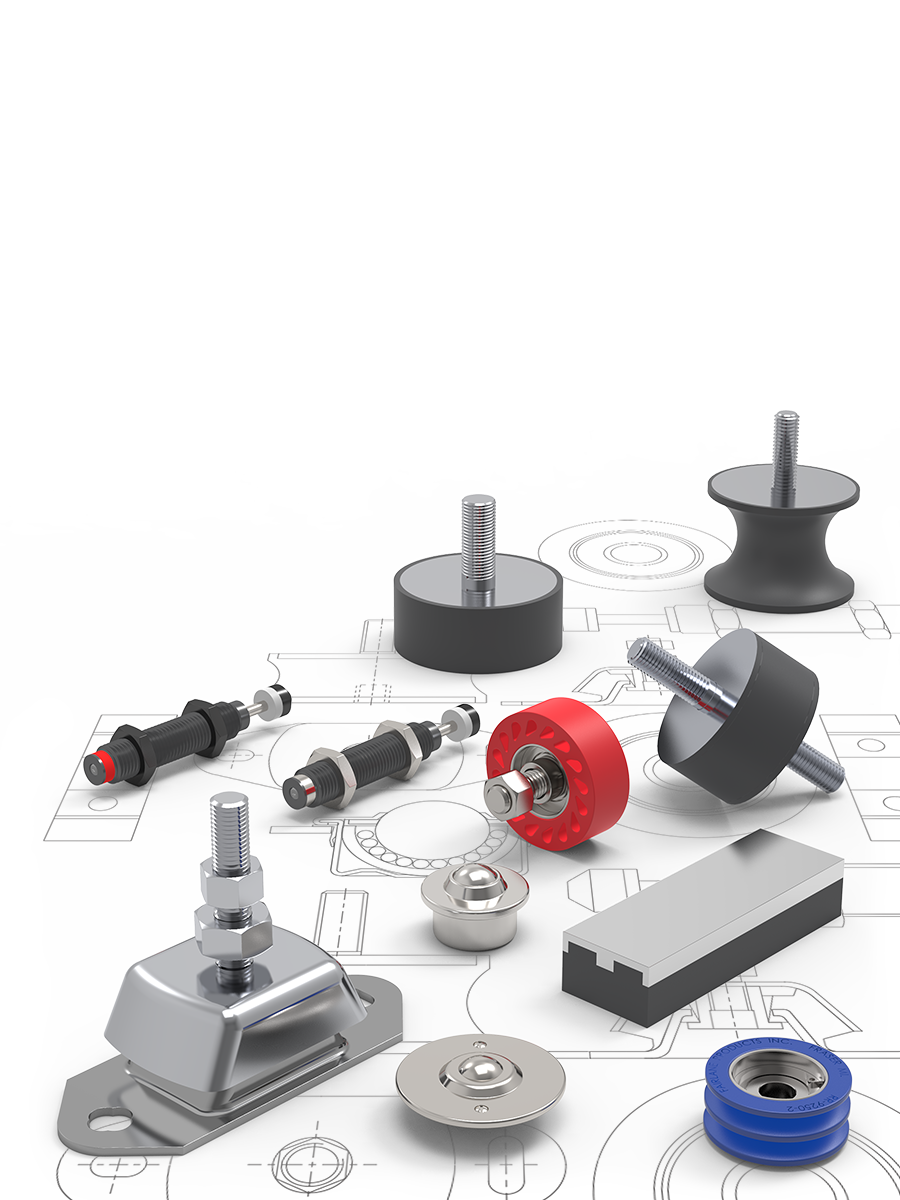
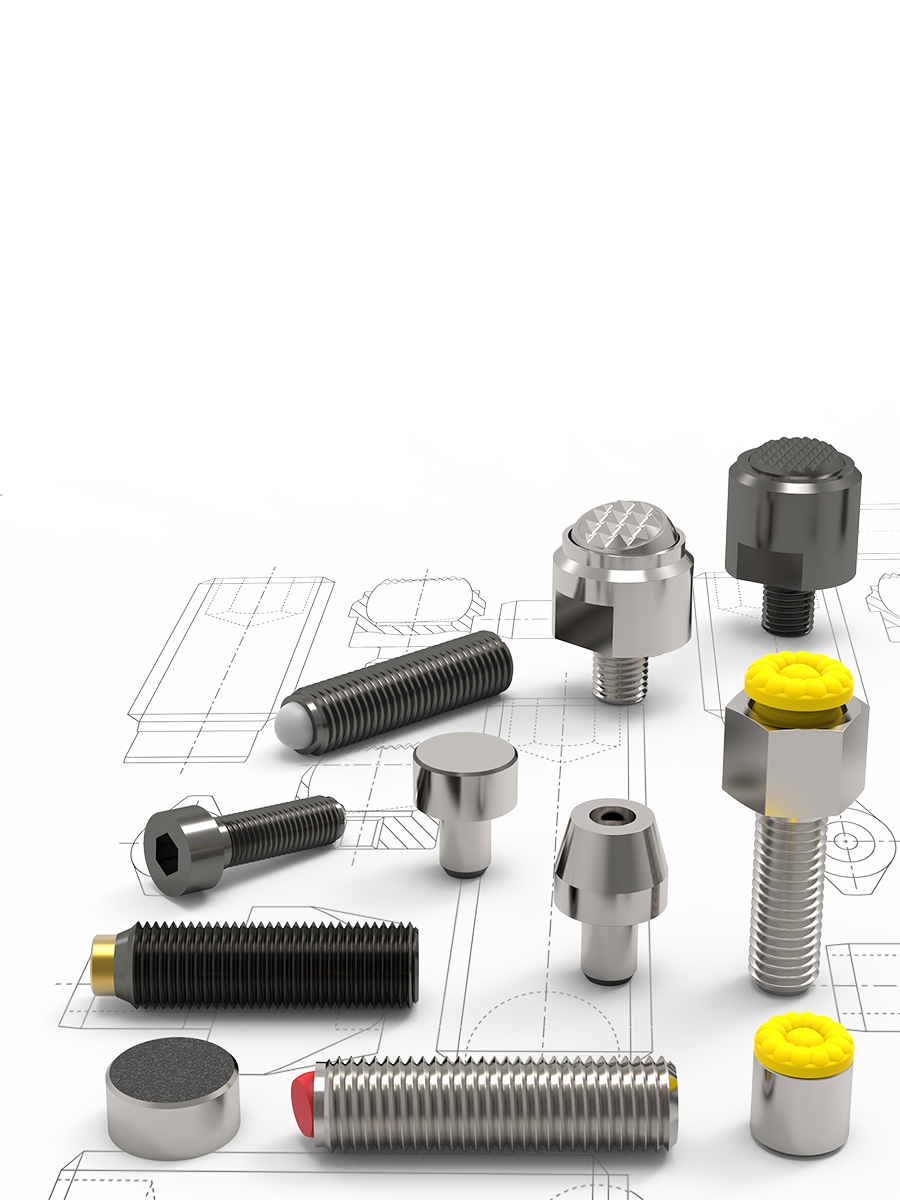
Wixroyd's comprehensive range of machine elements, standard parts, access components and workholding equipment contains a broad selection of sizes in materials including; stainless steel, steel, die-cast zinc as well as plastic. CAD models of Wixroyd components are available for free visit CAD download. For a free copy of the latest Wixroyd catalogue, the designers indispensable guide to A Range of Endless Possibilities, visit free literature.
Wixroyd are trusted by some of the best known design and manufacturing companies - helping them design, manufacture and assemble their products. Let our technical engineers help solve your unique application challenge.


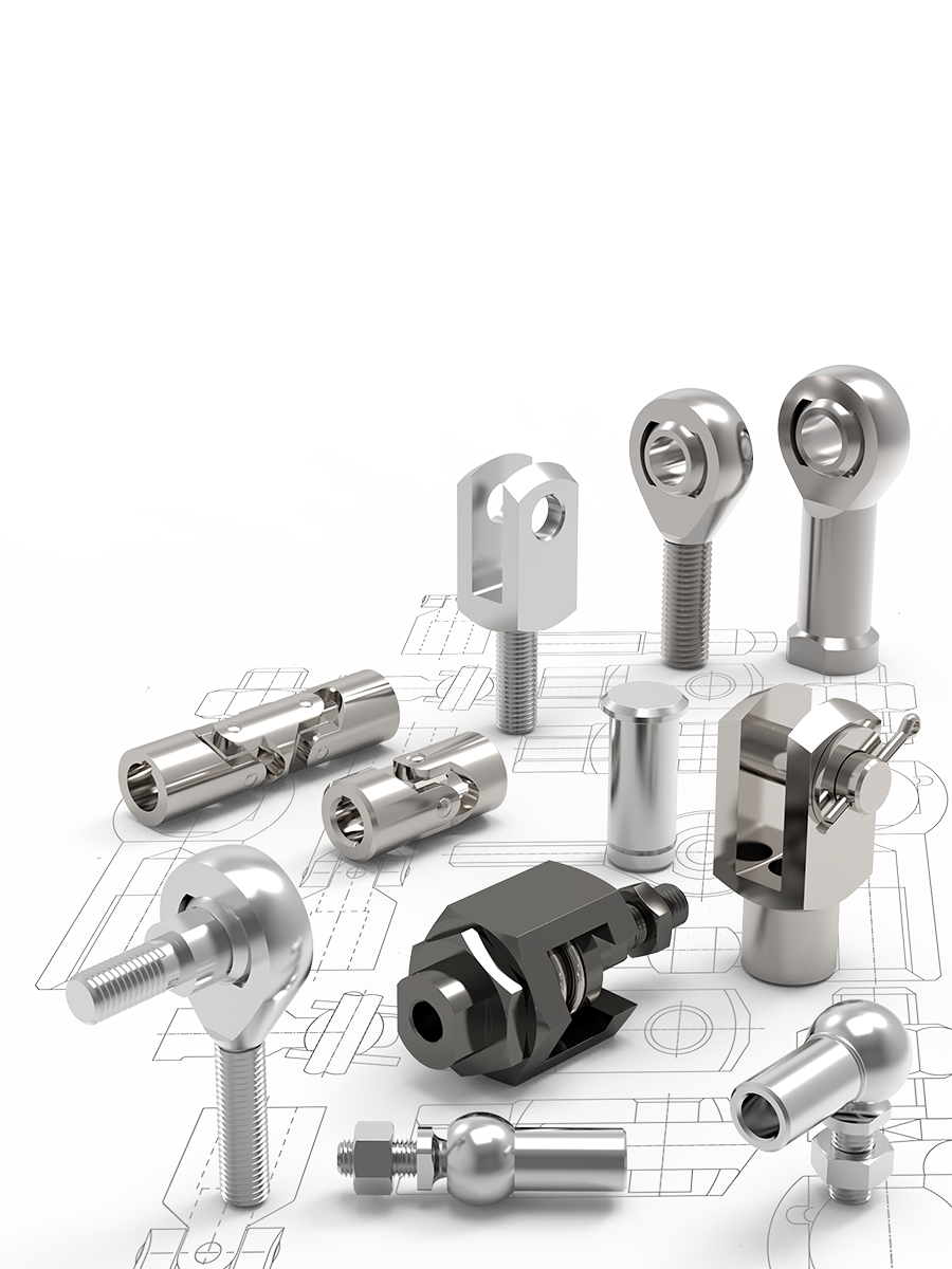
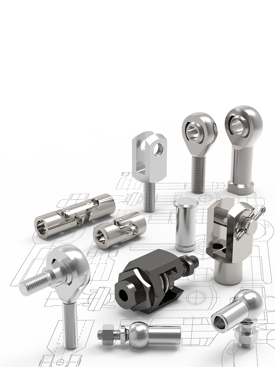
Heavy-duty Rod Ends with integral spherical plain bearing - Female. Both right and left hand thread available. To DIN ISO 12240-4.
Heavy-duty Female Rod Ends with integral ball bearing. Made from forged steel. Low maintenance required. Sizes according to DIN ISO 12240-4.
Heavy-duty Female Rod Ends with integral roller bearing. Made from forged steel. Sizes according to DIN ISO 12240-4.
Heavy-duty Female Rod Ends with integral ball bearing. Made from forged steel. Low maintenance required.
Heavy-duty Female Rod Ends with integral spherical plain bearing. Made from forged steel. Right & left hand thread available.
Maintenance free, Heavy-duty Female Rod Ends with stud.
Fully stainless steel and maintenance free heavy duty female rod end with stud.
Plain Spherical Bearings
A Made from Polyamide-PTFE-fibreglass-compound, maintenance free, absorbs any foreign particles.
B Ball made of bearing steel, hardened, ground, polished and hard chromium plated; ensures reliable corrosion protection.
C No Clearance - radial clearance 0-10µm.
D All Rod End housings made of gorged steel, tempered, extremely high load resistances.

Ball and Roller Bearings
A Radial clearance: 10-30µm, low friction.
B Inner ring made of bearing steel, hardened ball grooves, polished.
C Shields on both sides protect against rough dirt penetration.
D All Rod End housings are made of forged steel, case hardened bearing race.
E Low maintenance due to long-term greasing; especially suitable for high speed large swivelling angles or rotating movements

Rod Ends and Water - Stainless Steel Versions
Most of our Rod Ends are available in stainless steel as standard. High grade AISI 316 stainless steel available on request.

Rod Ends with Integral Maintenance-free Spherical Plain Bearings
In many cases, Heavy-duty Rod Ends with integral spherical plain bearings are most often used. They are, above all, used for small swivelling or tilting movements at low speeds. They stand out for their high load capacity and can also be used for shock-like loads. The Rod End Ball slides on a plastic bearing shell, consisting of a glass fibre-filled nylon/teflon compound. This design assures a maintenance-free Rod End. Heavy-duty Plain Bearing Rod Ends have slight initial movement friction and virtually no clearance. The plastic material used has another advantage in that, it can absorb many foreign particles so that no damage can occur. The balls of Heavy-duty Rod Ends with Integral Spherical Plain Bearings are hard chrome plated. This reliable corrosion protection ensures, that the function of the rod end will not be affected by a corroded ball surface under humid operating conditions.
Rod Ends with Integral Ball Bearings
This design is especially suitable for high speeds, large swivelling angles or rotating movements with relatively low or medium loads. Prominent technical features are the low bearing friction, long-time greasing as well as the sealing against some dirt penetration (by means of shields on both sides). Under normal operating conditions, the Rod Ends are maintenance-free. Greasing nipples are provided for lubrication, in case of rough operations and maximum loads. To avoid incompatibility with the production lubrication, we recommend lubrication with a calcium-complex-soap-grease. A special heat treatment procedure gives the Rod End housing a raceway hardness, adapted to the anti-friction bearing, ensuring at the same time high stability with changing loads.
Rod Ends with Integral Roller Bearings
This design, based on the structure of a Self-aligning Roller Bearing, is preferably used for high speed, large tilting angles or rotating movements under high loads. Compared to rod ends with ball bearings, Rod Ends with Self-aligning Roller Bearings essentially have higher basic load ratings. This design is equipped with a cage to minimise the rolling friction and heat build-up. These Rod Ends, with long-time lubrication are under normal operating conditions maintenance-free. Greasing nipples are provided for lubrication in case of rough operations and maximum loads. To avoid incompatibility with the production lubrication, we recommend lubricating with a calcium-complex-soap-grease. Shields on both sides limit dirt particles from penetrating into the bearing. The Rod Ends with Roller Bearings are subjected to a special heat treatment to obtain a raceway hardness adapted to the antifriction bearings, ensuring at the same time a high stability with changing loads.
Radial Static Load
The ultimate Radial Static Load rating is measured as the failure point, when a load is increasingly applied to a pin through the Rod End's bore and pulled straight up while the rod end is held in place. Note that, the actual rating is determined by calculating the lowest of the following three values:
1. Raceway material comprehensive strength (R value)
R = E x T x X
2. Rod end head strength (H value, cartridge type construction)

3. Shank strength (S value)
Male Threaded Rod End
S = [(root diameter of thread2 x .78) - (N2 x .78)] x X
Female Threaded Rod End
S2 = [(J2 x .78) + (major diameter of thread x .78)] x X

E = Ball diameter
T = Housing width
X = Allowable stress
D = Head Diameter
N = Diameter of drilled hole in shank of male rod end
J = Shank diameter of female Rod End
Axial Static Load
The Axial Static Load capacity is measured as the force required to cause failure via a load parallel to the axis of the bore. Depending on the material types and construction methods, the ultimate Axial Load is generally 10-20% of the ultimate radial static load. The formula does not account for the bending of the shank due to a moment of force, nor the strength of the stake in cartridge-type construction.
Axial Strength (A value)
A = .78 [(E + .176T)2 - E2 ] x
X = Allowable Stress (see table)
E = Ball diameter
T = Housing width

Request A Free Catalogue Today!
Explore a huge range of components from Spring Plungers to Clamping Systems with our free Design Elements, Access Components and Workholding catalogues.
Email Newsletter
Be the first to receive the latest news and exclusive offers via our newsletter.
Alexia House, Glenmore Business Park
PO19 7BJ Chichester
United Kingdom
0333 207 4497
sales@wixroyd.com
Route via Google Maps
Company registration no: 00496138
Company VAT number GB 408154022


