Lifting Bolts from Wixroyd
What is...
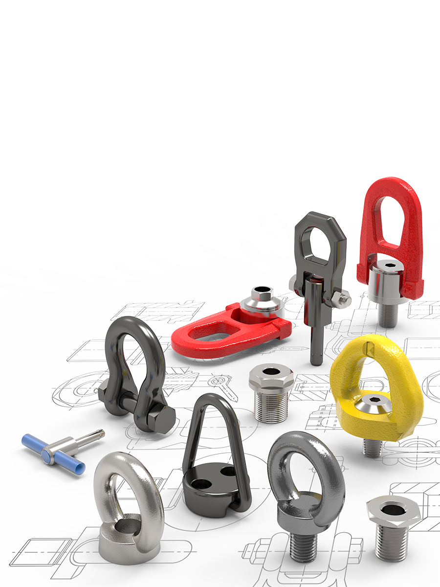
Lifting Bolts are metal bolts with an eye, specifically designed for lifting at an angle of up to 45° from the thread. Their main use is for permanent mounting to components such as motors, switchgear cabinets and gears as well as for the transport of such equipment. We also offer specialist Fall Arrest Lifting Bolts, suitable for supporting personnel during maintenance. Wixroyd Lifting Bolts are available in both male and female styles and are made from annealed, zinc plated forged steel, stainless steel or high tensile steel for our Fall Arrest Lifting Bolts.
Please refer to our comprehensive technical page for full safety information on the use of Lifting Bolts. We also include helpful application images in our datasheets and catalogue to help with your application.


Female Lifting Bolt made to DIN 582 standard; inch versions available as standard. Made from zinc plated, annealed forged steal with machined contact face.
Coarse thread Female Lifting Bolt made from stainless steel (A4, AISI 316) to DIN 582 standard. Inch versions are also available as standard.
UNC thread female lifting bolt made from zinc plated, annealed forged steel to DIN 582. Hot dipped galvanised version for more demanding applications are available on request.
Male lifting bolt made from zinc plated, annealed forged steal with machined contact face. DIN 580 compliant. We offer also inch versions as standard.
Coarse thread Male Lifting Bolt made from stainless steel (A4, AISI 316) to DIN 580 standard. We have inch versions readily available as well.
UNC thread male lifting bolt made from steel (C15) with hot dip galvanised zinc plating. Designed for use where the load is pulled in direct of the thread.
For use by harnessed personnel when conducting maintenance. Made from corrosion resistant, high tensile steel with coarse thread. Single articulation of full 360°.
Associated Products
Male Swivel Ring with single 360° articulation and coarse thread. Made from high tensile steel of strength class>8. Features automatic position recovery to orient with sling direction.
Female Swivel Ring with single 360° articulation and coarse thread. Made from high tensile steel of strength class>8. Features automatic position recovery to orient with sling direction.
Self-locking Quick-lift Pin made from heat treated steel. Safety shackle prevents accidental locking/unlocking. For lift forces of up to 48Kn.
Assembly Instructions
Lifting Bolts are generally intended for permanent mounting to components such as motors, switchgear cabinets and gears, and for transporting these items of equipment
1. They must be used by qualified personnel, trained to current European Standards on the place of use. Lifting Bolts must be permanently marked with a raised manufacturer’s mark, material ID (e.g. C15E, A2 or A4), load-bearing capacity in axial direction (WLL in Kg), and with the CE symbol. Refer to the relevant table to determine the effect of lifting angles on the load capacity.
2. Check the fixing points to ensure correct bolt seating. Check for corrosion, wear and tear, deformation etc. at regular intervals and before each use.
3. The fixing point should be selected carefully so that the resultant forces are absorbed by the base material without any deformation. Screw-in depth for steel with a tensile strength of Rm >340 N/ mm², e.g. S235JR (1.0037); or GG 25 (0.6025 – without cavities or shrinkage): 1.5 x thread diameter (=L). For screw-in material with lower strength, use fixing points with greater screw-in length. Minimum screw-in depths recommended by the Liability Insurance Association: 2 x thread diameter in aluminum alloys 2.5 x thread diameter in light metal with low strength. For light metals, non-ferrous metals and grey cast iron, select the thread such that the load-bearing capacity of the thread corresponds with the requirements involving the base material. For through-holes, a nut (0.8 x d) should be fully and firmly bolted from the opposite side. If the thread length of the screw is sufficient, the use of an additional washer is recommended.
4. Select the location of fixing points carefully to ensure that any rotational effects or load shifts are avoided. Arrange the fixing point for a single strand sling perpendicularly above the center of the load. Arrange the fixing points for a twin strand sling on both sides and above the load center. Caution: Avoid turning or rotating movements during the lift! Position the lifting bolt such that no shear tension acts on the bolt. Any introduced force must act in the direction of the eye bolt plane.

5. The attachment surface must be flat. Maximum spot-facing of the thread hole = nominal diameter of the thread. Blind holes must be drilled to a sufficient depth to ensure that the contact surface of the eye bolt is fully seated.
6. Shock loads, tugs or vibrations may cause inadvertent loosening. Consider using a liquid thread lock agent such as Loctite making sure to observe the manufacturer’s recommendations. Always secure bolts which remain permanently at the fixing point, e.g. by gluing.
7. The end attachment must be freely moveable in the Lifting Bolt. When slinging and removing the end attachments (sling chain, round sling, wire rope), make sure that no pinch, shear, catch or impact points occur. Avoid damage to the end attachments caused by sharp-edged loads.
8. Temperature suitability; these Lifting Bolts may be used without restricting or impairing the load-bearing capacity within the temperature range from -20°C to +200°C.
9. The seating surface of the bolts must not be allowed to make contact with corrosive chemicals, acids or their vapours.
10. After initial installation and at intervals depending on use, however at least once every year, the continued suitability of the fixing point must be checked and inspected by an expert. This should also be done after any damage or other unusual incidents.
Email Newsletter
Be the first to receive the latest news and exclusive offers via our newsletter.
Alexia House, Glenmore Business Park
PO19 7BJ Chichester
United Kingdom
0333 207 4497
sales@wixroyd.com
Route via Google Maps
Company registration no: 00496138
Company VAT number GB 408154022


