Universal Joints General
What is...
Features
Overview
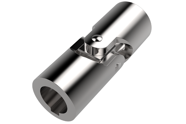
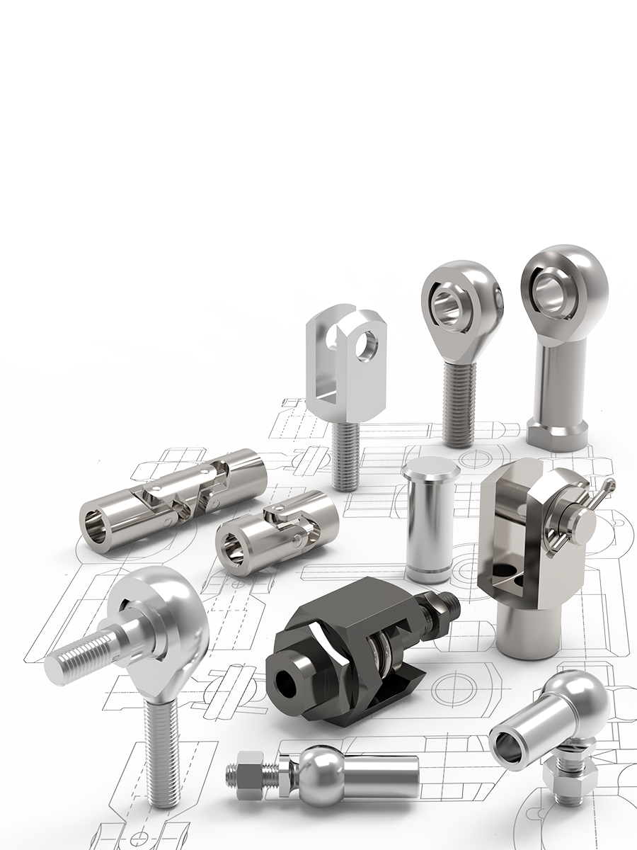
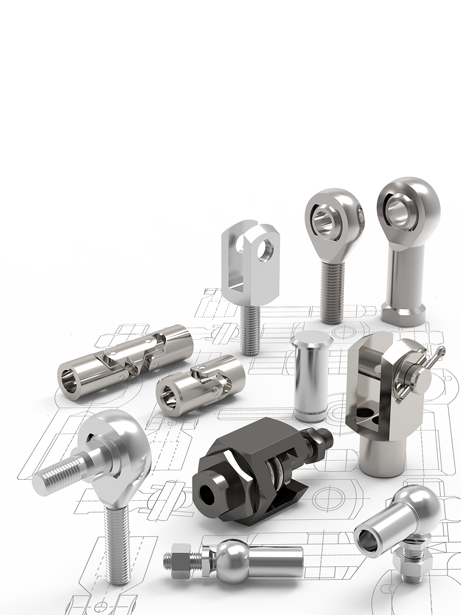
Single Universal Joint
Available with plain bearings or needle roller bearings. Plain bore and keyed bores stocked as standard; hex or square shaped bores on request. Bore diameters 6mm up to 50mm.

Stainless Steel Universal Joints
Single and double Universal Joints with plain bearings and plain bores. Keyed or hex or square shaped bores available on request. Bore diameter 6mm up to 30mm.
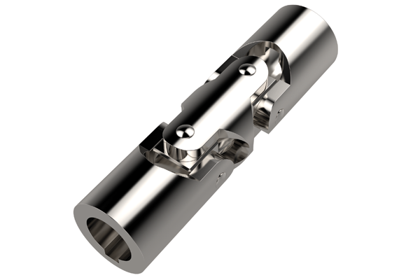
Double Universal Joints
Available with plain bearings or needle roller bearings. Plain bore and keyed bores stocked as standard: hex or square shapped bores on request. Bore diameters 6mm up to 50mm.
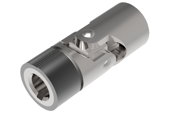
Quick Release Universal Joints
Quick charge mechanism on one end of the joint to allows rapid connection and release of the shaft; ideal when time is critical. Bore diameters 8mm up to 30mm.
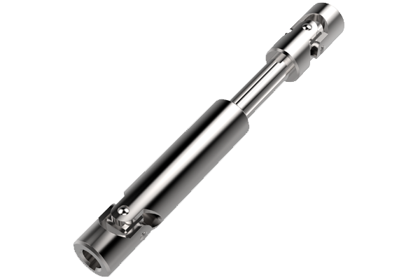
Telescopic Universal Joints
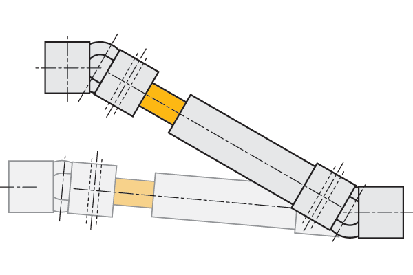
Two Universal Joints connected by a sliding splined shaft with the ability to extend, allowing adjustments in length during installation. Bore diameters 10mm up to 30mm.
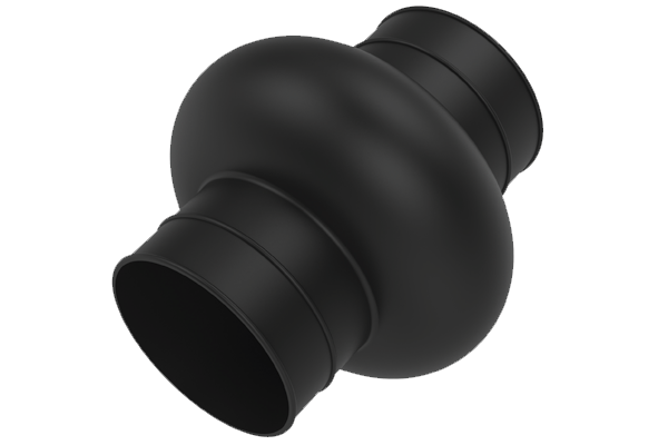
Universal Joint Bellows
Available for both single and double Universal Joints, bellows are used to cover and protect the joints. Available to protect joints up to 58mm outside diameter.
When one single joint is coupled with two shafts (of which the driving one is rotating at a constant speed) forming an angle, a periodic variation of the driven shaft is caused with exactly four fluctuations per revolution.
The difference between the maximum and the minimum speed of the driven shaft depends on the angle formed by the two shafts. The difference grows with an increase of the angle a°. To have homokinetic transmission, either two opposite single joints (ensuring that the two central yokes lie on the same plane and the angles are equal) or double joints need to be fitted. The irregularity caused by the former articulation is cancelled by the latter. The overall length resulting from the coupling of the two single joints can be reduced by using a double joint. In other words, the double joint is to be considered as the shortest homokinetic transmission.
For low speed applications (Max. 1000 rpm), joints with plain bearings (rubbing bearings) are suggested. They are able to support shock loads, motion reversals, irregular runnings and relatively high torques. The working angles must be restricted when using at speeds between 500 - 1000 rpm. Please consult our technical department if you have such an application.
For high rotation speeds, relatively low torques or wide angles, joints with needle roller bearings are preferred. They can reach 4000 rpm dependent on the angle.
Installation
Dynamic basic load ratings of Plain Bearing Rod Ends
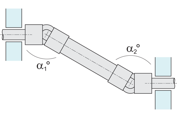
To obtain a uniform rotary motion, always use either two opposite single joints or one double joint a1 = a2.
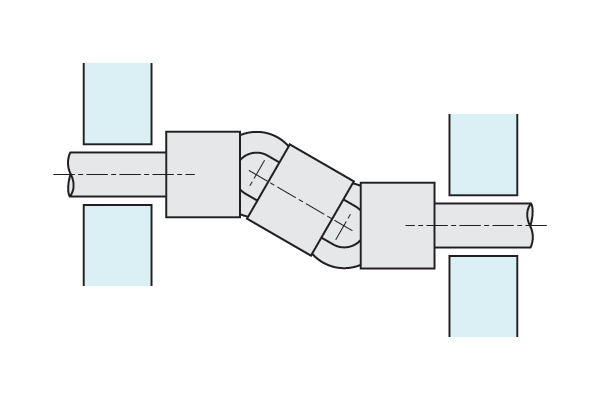
The pillow blocks supports should be positioned as close as possible to the joints.
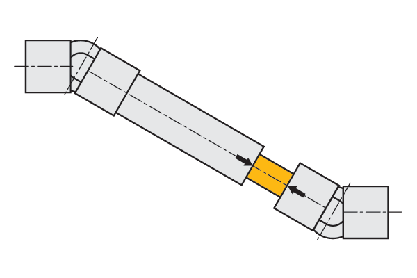
When using two opposite single joints, ensure the alignment of the inside yokes.
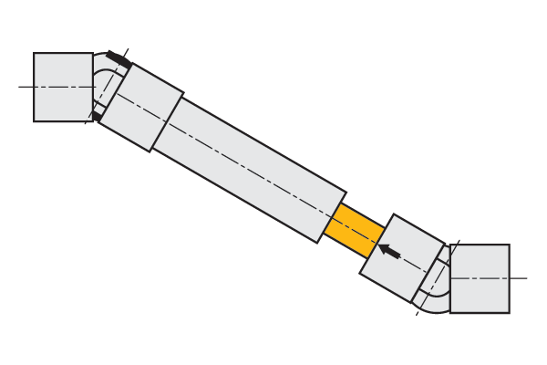
In extensible transmissions make sure that the arrows are perfectly aligned.
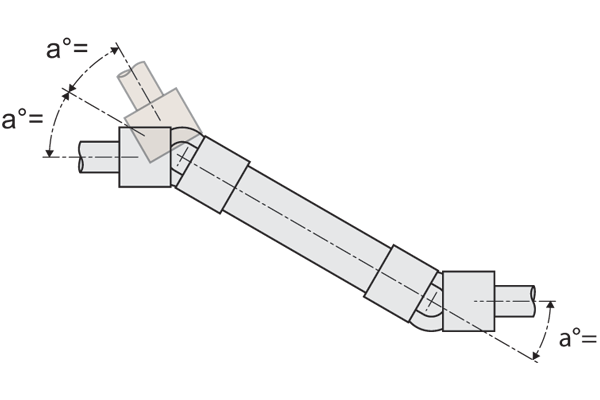
It is essential that the two bending angles a° are equal.
Technical Specs
How to read diagrams
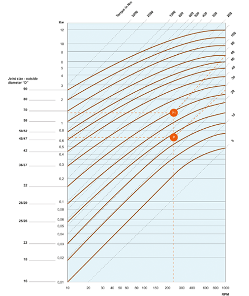
The joint capacity to transmit a regular torque at a constant load with no shocks, for a long period, mainly depends of the number of revolutions per minute and the inclination angle a° of the two axes. The diagram on the following pages are based on this. Each curve corresponds to the joint size (outside diameter "D") and represents the torque that the joint can transmit depending on speed and working angle a°.
The diagrams can be directly read if angle (a°) is 10°. For wider angles, torques are reduced, therefore these are to be corrected using the correction values (F) relating to the angle shown in the table.
Important Note: Diagrams' values are merely indicative and refer to the single joints only. When choosing a double joint, you have to consider that they can transmit a torque about 10% lower than the same sized single joints. Each application has its own particular motion characteristics, such as: shock loads, motion reversals, connected masses, kind of starting presence of elastic joints, stops and starts, etc..., that have to be considered when choosing the joint.
| Working angle a° | Correction value F |
| 5° | 1,25 |
| 10° | 1,00 |
| 15° | 0,80 |
| 20° | 0,65 |
| 25° | 0,55 |
| 30° | 0,45 |
| 35° | 0,38 |
| 40° | 0,30 |
| 45° | 0,25 |
Example
Known:
Power = 0,65 kW
RPM = 230
With working angle a°, F = 1, we get point P. Torque = 27Nm corresponding to joint size "D" = 25/26mm = Types 65170.W0016 and 65172.W0012
With working angle a° 30°, F = 0,45 (kW 0,65: 0,45 = 1,44 kW) we get point P1 Torque = 60 Nm corresponding to joint size "D" = 32mm = Types 65170.W0020 and 65172.W0016
Consider that:

Torque Ratings for Plain Bearing Universal Joints
Email Newsletter
Be the first to receive the latest news and exclusive offers via our newsletter.
Alexia House, Glenmore Business Park
PO19 7BJ Chichester
United Kingdom
0333 207 4497
sales@wixroyd.com
Route via Google Maps
Company registration no: 00496138
Company VAT number GB 408154022
