VacMagic VM300 - 19730 - Mounting The Base Unit
Installation
Option 1 - Preferred method for mounting the base unit
- Identify the locating pins and secure with 4 mounting clamps.
- Baseplate is now ready for connection of air supply.

Option 2 - Mounting using internal slots
1) Remove 6mm bolts (2 each), securing locating pins from the bottom side of the unit, and loosen top plate mounting bolts. Remove locating pins, mounting bolts and top plate.
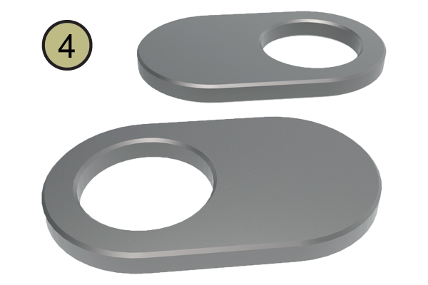
2) Identify the base plate and secure using special mounting washers.
3) Prior to installing top plate, ensure there are no foreign objects on either of the mating surfaces and all three o-rings are properly seated. Install top plate and loosely install mounting screws.
4) Insert locating pins and adjust diamond pin 90° to solid pin. Please be aware there is no practical method of installing the 6mm bolts used to secure the locating pins once the base is mounted. (A subplate with clearance holes may be used if necessary.)
5) Securely tighten all 9 top plate mounting bolts.
Important Note: One loose top plate bolt may interfere with pallets precisely locating on rest pads, preventing 100% vacuum.
Option 2 may be necessary if mounting more than one unit side by side.
Base alignment pins may be installed to locate off t-slots or precise bores in sub-plate. Remove top plate and secure with provided mounting screws.
6) Base plate is now ready for connection of the air supply.


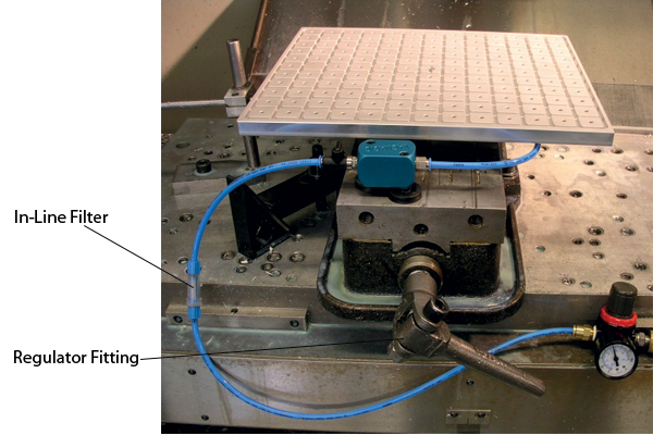
The in-line filter is provided to identify any contaminants in the air supply.
Manual Machines
Note: Air requirements should be between 70-100 psi with a minimum flow of 2CFM. Pressure below 70 or above 100 psi will reduce maximum vacuum force.
1) Install regulator fitting to regulator. Connect 6mm blue tubing to front of base unit (supply valve) and regulator fitting. Mounting brackets included to aid in routing lines.
2) Secure tubing close to the base unit to prevent undue stress on supply valve.
3) Place blank pallet on unit, turn on supply valve, and vacuum indicator retracts. (Refer to troubleshooting section if indicator is not fully recessed).
System is ready for use.
Manual Machines
Perform steps 1-3 above for manual machines
4) Remove power from the machine.
5) Mount the LPTS at convenient location, usually to the rear of the machine.
6) Connect 4mm blue tubing to the front base unit and fitting on the LPTS.
7) Connect the LPTS in series with the selected cutoff circuit.
8) Restore power and check all the air connections for leaks.
9) Adjust the trip screw located on top of the LPTS between the two prongs; synchronise with the low-vacuum indicator on the front of the base unit.
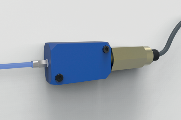
Important Note: Method of synchronising the LPTS with the low-vacuum indicator. With LPTS connected to the door switch interlock, slowly reduce the airflow with the supply valve until the low-vacuum indicator starts to protrude. At this point, adjust the trip screw until the machine shuts down. Increase the airflow and the machine will resume function. This should be done several times to ensure proper settings.
System is ready for use.
Review checklist prior to use
Base unit is identified and securely mounted to the machine table.
Top plate bolts are tight.
Check all air lines for leaks.
Air supply is 70-100 psi.
Low Vacuum Indicator is operating properly.
LPTS is operating properly (if installed).
Applications
- Quick change
- Maximise productivity
- Easy installation
- Precise repeatability
- Reliable and easy to use
- No pump required

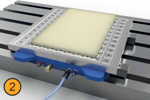
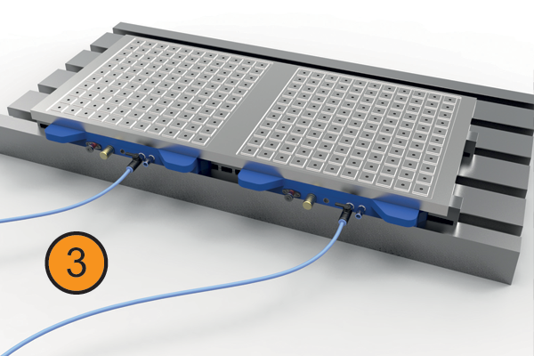
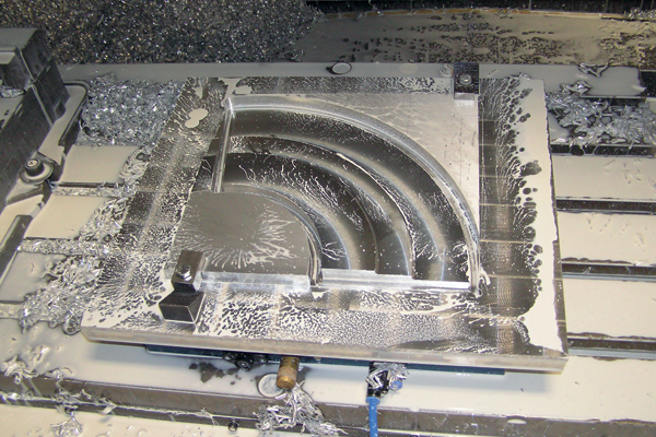
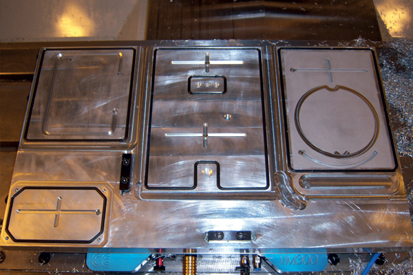
- Low profile base unit quickly mounts to machine table. Operates with 70 PSI standard workshop air.
- Workpiece placed over rubber cord and pushed down to create a vacuum. Now ready for machining.
- Two systems placed next to each other for holding larger pieces.
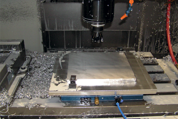

Technical Specs
Maintenance
Very little maintenance is necessary to keep your system up and running. Using general housekeeping practices will ensure your system operates properly for years to come.
- Brass filters may require periodic cleaning to prevent clogging and obstructing the airflow. Remove the filters and soak in a cleaning solvent, and apply compressed air from the backside of the filter. This should be done in a safe manner to avoid personal injury to yourself or other personnel. After this, re-install the filters.
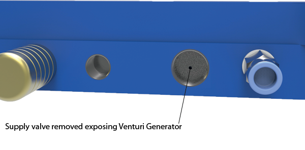
- The Venturi Generator may become obstructed with foreign objects or gummed up from coolant if the system has not been used for a while. Simply remove the supply valve and check/remove any small objects that may be interfering with the air supply. While the supply valve is removed, use a 0.035 (0.9mm) pin to clear any build-up that may have accumulated in the Venturi Generator (see image below).
- The Low Vacuum Indicator may also require periodic cleaning. Remove this and clean with light oil before re-installing.
- A visual inspection of all o-rings and white gasket material should be done on a regular basis: o-rings monthly, white gasket material weekly.
Troubleshooting
This is a very simple operating system, any problems can be easily rectified with the information contained in this manual or by contacting us directly.
Check air pressure.
Ensure gasket material is protruding above the fixture plate and continuous with no gaps.
Clean brass filters.
Check front of Venturi Generator for obstructions.
Ensure locating pins are fully seated (diamond and solid).
Through hole for vacuum pallets should be a minimum of 0.25 inch diameter.
Check that all top plate mounting bolts are tight and below the surface.
Check air lines for leaks.
Check workpiece for flatness.
Check exhaust air for restricted flow.
Additional information
- This Venturi Generator produces approximately 12-13 pounds of vacuum per square inch.
- Increasing friction between your workpiece and the vacuum pallet will produce additional holding force. Using an adhesive backed "sandpaper" product on the vacuum plate or pins with sharp points protruding slightly above the surface will aid in difficult applications.
- When using more than one system for large applications, we recommend keeping each system independent from each other.
- Apply a small amount of silicone to secure the white gasket material in the slot. A very small dap is all that is required, as not to interfere with compression characteristics.
- When using the Vacmagic as a pallet changer or when a vise is mounted to a blank pallet, aggressive machining operations can be accomplished. In this configuration, the vacuum being produced is approximately 1,500 lbs. What makes the unit so strong are the two 12 mm locating pins that would have to bend or snap to break the vacuum seal.
- The standard vacuum pallet has 140 holes (4 mm) that can be used for locating pins or small edge clamps.

Mounting a vise on the blank pallet will eliminate the time it previously took to identify before every use.
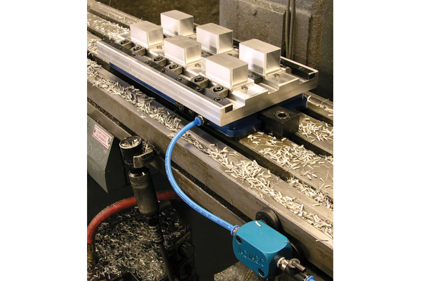
12x20 Fixture Plate
Features
Contents of kit







1. Base unit (SL0430.45175)
2. Vacuum pallet (SL0430.45150)
3. Blank pallet x2 (SL0430.45130)
4. Special mounting washers x4 (MB45055)
5. Low pressure trip switch (LPTS) (MB45040)
6. 4mm & 6mm Supply line (MB45080 and MB45085)
7. Base unit mounting clamps x4 (MB22851)
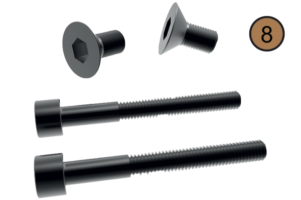
8. LPTS mounting screws x2, FHCS for alignment pins x2
9. 10 ft. Gasket material (black) (MB45110)
10. Extra o-rings x3 (MB45045)
11. Base alignment pins x2 (MB45075)
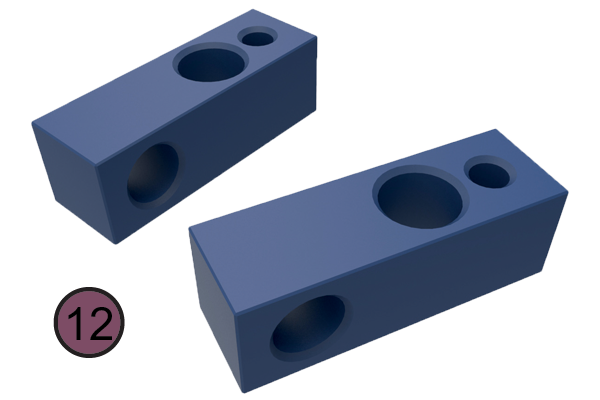
12. 4mm & 6mm tubing mounting brackets x2
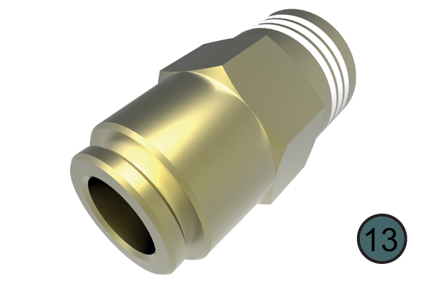
13. 6mm Supply line regulator fitting (MB45050)
14. Inline Filter (MB45015)
Replacement parts for 19730
| Description | Part No. |
| Brass Filter | MB45010 |
| In-Line Filter | MB45015 |
| Mounting Bracket w/4mm & 6mm holes | MB45020 |
| Locating Pins (1 tapered & 1 diamond) | MB45025 |
| Low Vacuum Indicator w/spring | MB45030 |
| Spring for Low Vacuum Indicator | MB45031 |
| LPTS Switch | MB45035 |
| Low Pressure Trip Switch Assy (LPTS) | MB45040 |
| “Vacmagic O-Rings” (3/pk, 2 small & 1 large) | MB45045 |
| Supply Valve | MB45050 |
| Special Mounting Washer | MB45055 |
| LPTS Fitting (Base Unit) | MB45060 |
| LPTS Fitting (Block) | MB45065 |
| Bushings for Custom Pallets (2/pk) | MB45070 |
| Base Alignment Pins (2/pk) | MB45075 |
| 4mm Blue Tubing (15 ft/pack) | MB45080 |
| 6mm Blue Tubing (12 ft/pack) | MB45085 |
| 6mm Tubing QD Fitting for Regulator | MB45090 |
| Assorted Mtg. Hardware for location pins, alignment pins & LPTS block | MB45095 |
| Vacmagic System including 1 vacuum pallet, 2 blank pallets & 4 mounting clamps | MB45101 |
| Vacuum Gasket 0,170” dia. (5 ft/pack) - Black (for long machine cycles & aggressive coolants) | MB45110 |
| Vacuum Gasket 0,170” dia. Custom Lengths (by the ft)- Black (for long machine cycles & aggressive coolants) | MB45111 |
| Vacuum Gasket 0,125” dia. (5 ft/pack) - Black (for long machine cycles & aggressive coolants) | MB45118 |
| Vacuum Gasket 0,170” dia. (by the ft)- White (for small parts, water based coolants or dry running) | MB45114 |
| Vacmagic Blank Pallet | MB45130 |
| Vacmagic Vacuum Pallet | MB45150 |
| Vacmagic Base Unit including 4 mtg clamps | MB45175 |
| Large Mounting Clamp | MB22815 |
Knowledgebase Questions
Yes, if the component has a good amount of surface area for the vacuum to work with you can use the Mitee-bite Multi-power Vacuum Unit. This model has twelve recessed pockets on the side of the vacuum receiver which allows multiple units to be joined together to make a large vacuum.
If you join two vacuums units together, this will give you the surface area needed to clamp your components of the size mentioned above. If you are machining with lateral forces we suggest you use the clamping stops, such as the sliding stop, which can be secured in the vacuum base using its M6 holes.
Vacuum clamping is preferred when components are too thin to use traditional methods, as long as you have a large surface area then vacuum clamping is ideal. Providing cost effective work holding solutions, suitable for prototype work, increasing productivity and minimising damage to the work piece.
Vacuum clamping is suited to holding wood, plastics, aluminium and other non-ferrous metals which require quick and simple machining.
Yes, if your machine can offer 70-100 PSI then you can operate your Mitee-bite Vacmagic VM300.
Opening force / clamping force = no of power clamps required
Our part no CL1690.H0184 power clamp has a 43 kN. See our example below;
100 Ton (1000000 N / 43000N = 24 power clamps per side
Email Newsletter
Be the first to receive the latest news and exclusive offers via our newsletter.
Alexia House, Glenmore Business Park
PO19 7BJ Chichester
United Kingdom
0333 207 4497
sales@wixroyd.com
Route via Google Maps
Company registration no: 00496138
Company VAT number GB 408154022
